Light sources
Soldering
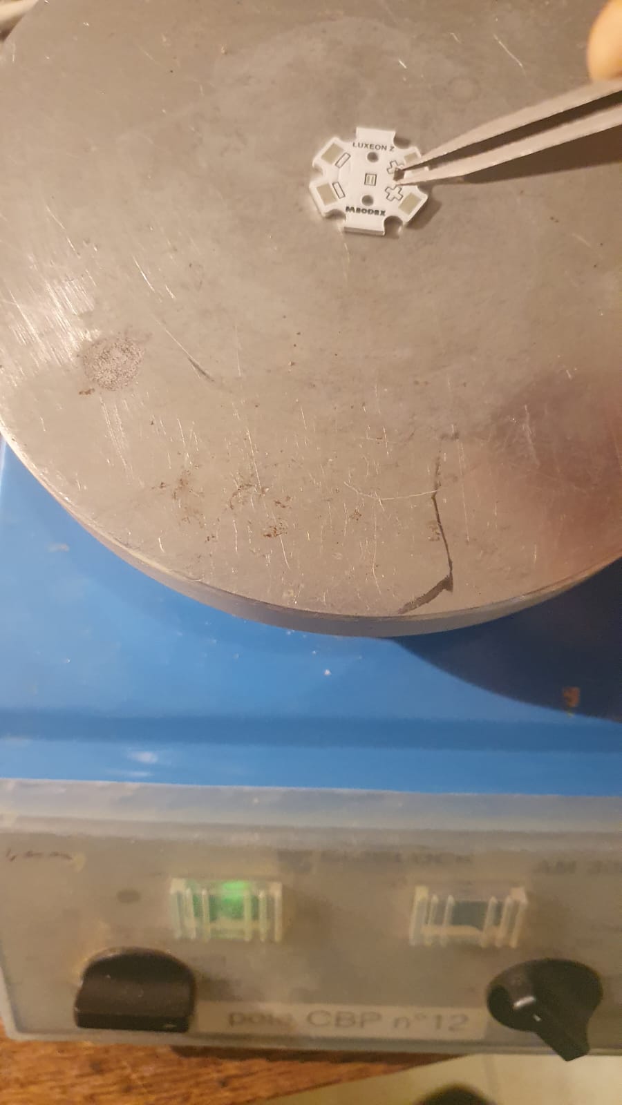
Solder LEDs to star PCB. This first step is the hardest of the tutorial. First tin-coat the electrodes of the LED. Make sure the electrodes are not gated by the tin. Let the PCB star warm to 200°C on a heating plate. Then connect the LED to the PCB star, apply pressure. Take the mounted LED from the plate and let it cool down. Solder the electric wires to PCB.
Control
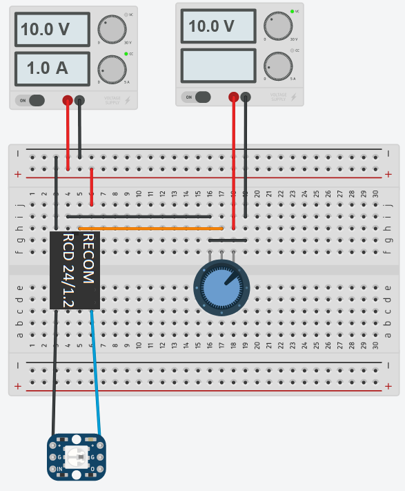
If you do not yet have access to LED drivers(example: 1, 2.), the first option is to build a minimal LED controller circuit. You will need the RECOM DC/DC converter, a potentiometer and electric wires. Use a regulated power supply to power the RECOM and another for the potentiometer.
The second option is to build an LED driver. We are currently develping a board allowing to build the LED controller. You can find the first design files HERE - v1 and the second version HERE - V2. Disclaimer: This work is not stable yet (beta).
You can follow the instructions in this repository to control the LEDs.
Assembly and test
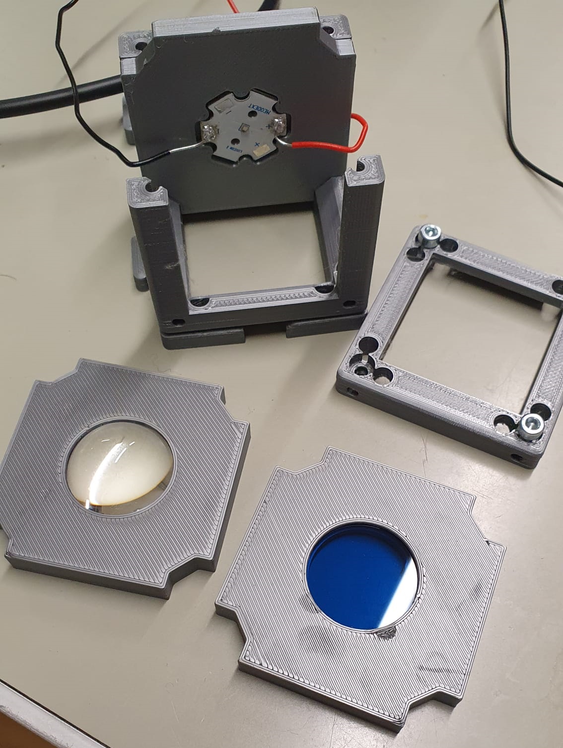
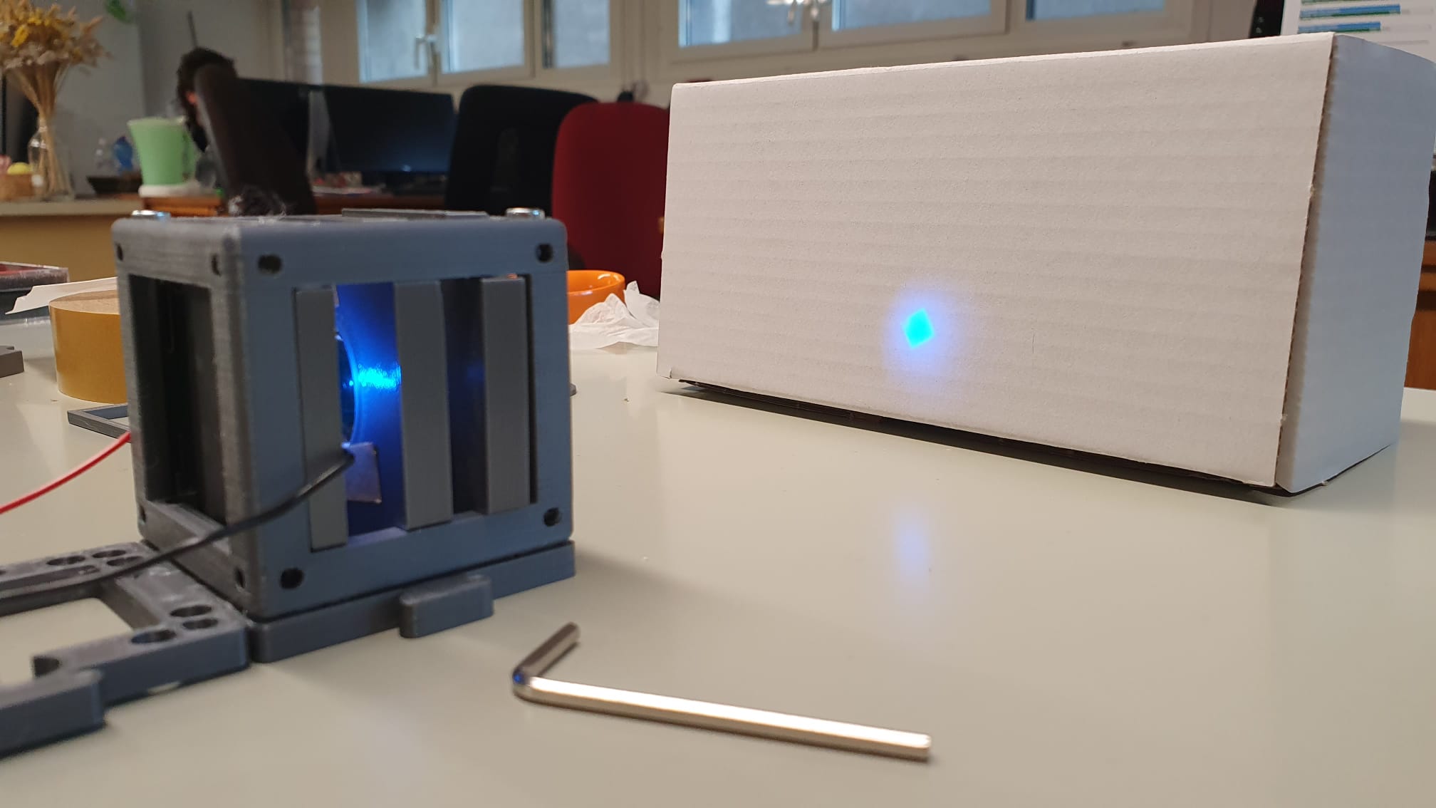
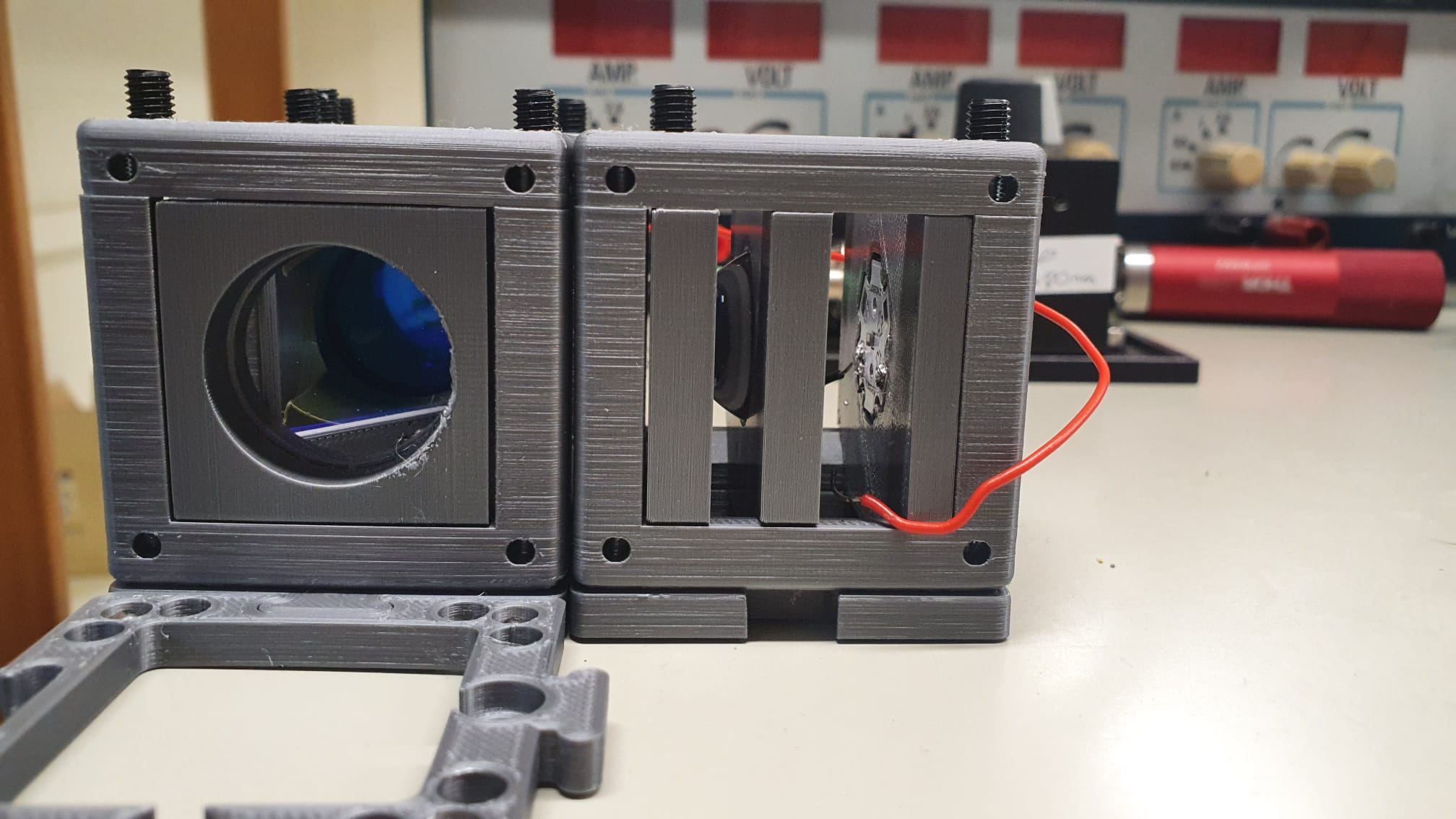
Mount the blue and purple LEDs on the UC2 star holder according to UC2 documentation. Add the lens mounted on the holder in front of the LED, and the filter mounted on the filter holder.
Make sure that you can observe the image of the chip on a white surface
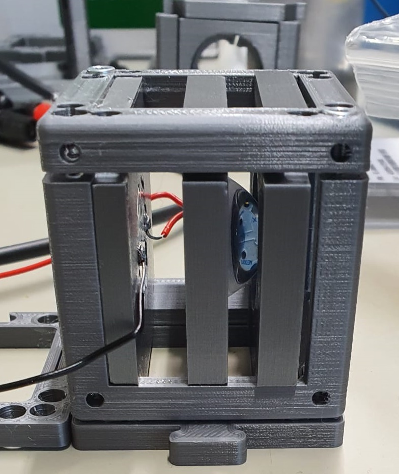
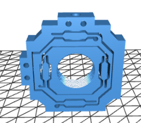
Notes: the 3 mounts don’t hold still once the base cube it closed. We had to use double-sided tape to fix the LED mount. One other option is to increase the size of the mount slightly to tight it with the screws when closing the cube. The clamp to hold the filter works fine but is not sufficient to hold the lens which has a different geometry. We designed a new lens holder that includes threading compatible with Thorlabs holders (1 inch) HERE.
LED combination
Mount the dichroic filter on the dichroic filter holder accroding to UC2 documentation
Combine the two LEDs with the dichroic filter according to this scheme:
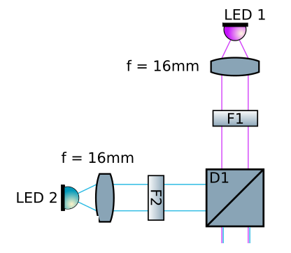
With LED 1, LED 2, F1, F2, D1, lens.
Optical fiber injection
The 2 LEDs are combined, however the size of the light beam is on the centimeter scale, but the optical fiber’s aperture is 400µm. We use a microscope objective to reach the spot size required to inject in the fiber. (for now: 40x/0.65)
Prepare the 3D parts for the fiber injection: XY fine displacement objective holder and lens holder to hold the SMA fiber adapter. You can find more info on UC2 documentation for fiber coupler. Mount the objective in one cube and the fiber holder in another and assemble them.
Note: The XY objective holder is great ! The only issue is that the rest position is centered and the screws only allow positive X or Y displacement. We attached an elastic so that the rest position is tight to the corner (minimal X and Y position). That way it is possible to explore the whole X-Y displacement space allowed by the 3D piece with only 2 screws.
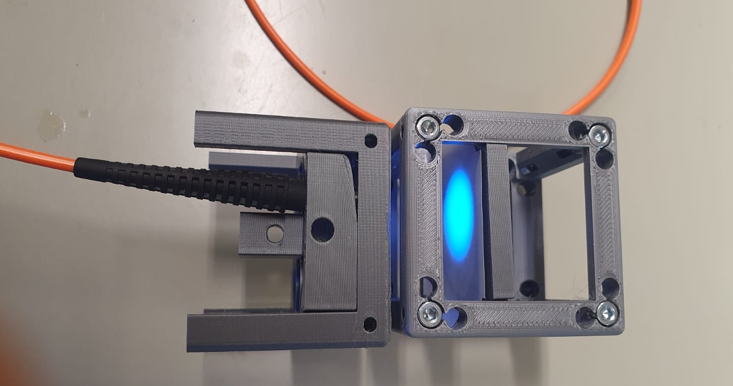
Adjust the focal distances so that the spot from the LEDs matches the entrance of the microscope objective and the output of the objective matches the aperture of the fiber. (TODO: give more details here)
Check the output of the fiber and the homogeneity of the spot. The blue light is brighter so you can play with the potentiometers to see the 2 colors separately.
Imaging
1 - Start to build the second part of the microscope : connect the other end of the fiber on an other UC2 cube.
2 - Mount a dichroïc filter on a dichroïc holder cube (UC2 documentation) and place it after the fiber according to the schema :
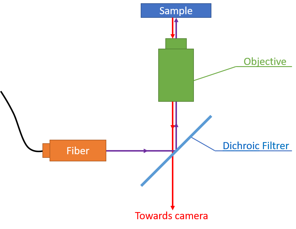
3 - Construct the upper part of the scheme with the objective and the sample holder : we use XY fine displacement objective holder in one cube followed by Generic sample holder in another cube.
4 - Combine the dichroïc filter and the objective-sample part. The dichroïc filter transmits light below the cut-off wavelength and reflects ligth above the cut-off. The fluorescence emission has a higher emission wavelength than the excitation. The incomming light from the fiber will be reflected by the dichroïc filtrer and go through the objective. Then the light emitted by the sample will be collected by the objective and pass the dichroïc filter without reflexion.
5 - Print your camera 3D holder model from the git (Search with Ctrl+F), and mount your camera in it. We use a Daheng MER2-503-36U3C camera with Camera Cube (Allied Vision Alvium). On the Daheng camera, the fixation consist on three screws :
Note : We also use an IDS camera, and since there is not a camera holder for it, we use the Camera Insert Allied Vision Alvium adjustable.
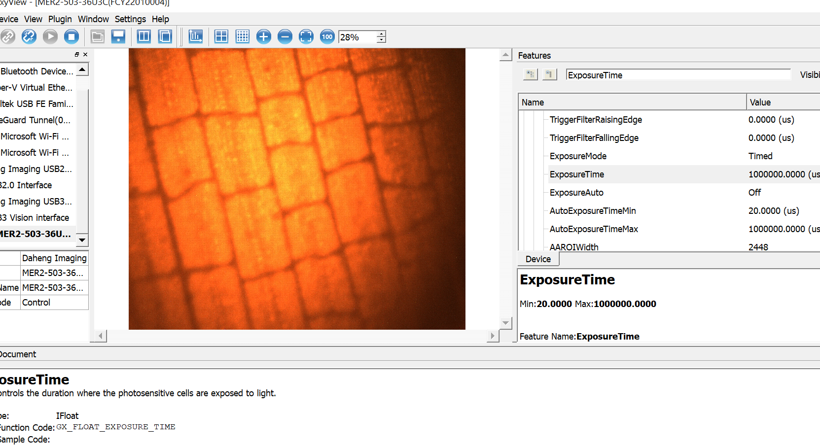
6 - Mount an adapted lens on the camera (we used a focal of f = 150 mm). Position the lens to conjugat it with the camra sensr: to do so, observe a net image of an object positionned 10 meters away from the camera. Then, align the lens and camera with the microscope objective and move the sample along the Z-axis to adjust the focus. To observe the sample, you may need to adjust your’s camera parameters, like the exposure time and the gain.
You can follow the instructions in this repository to automate the movement of the sample.
Note : Since the lens is heavy, we put a UC2 cube at the end of it with a lens holder to keep it straight.
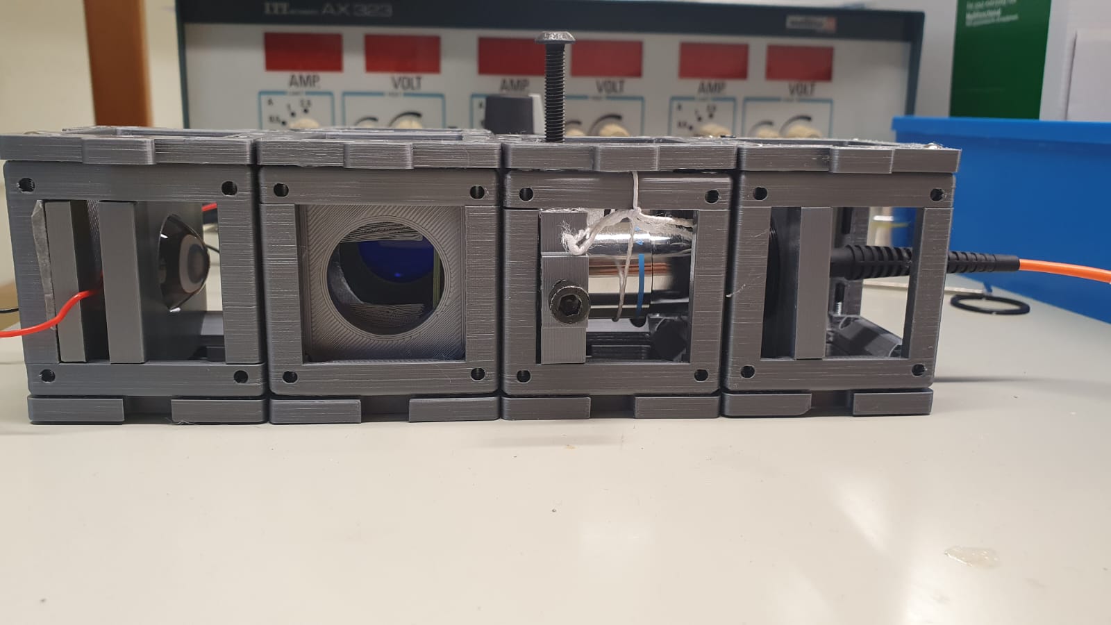
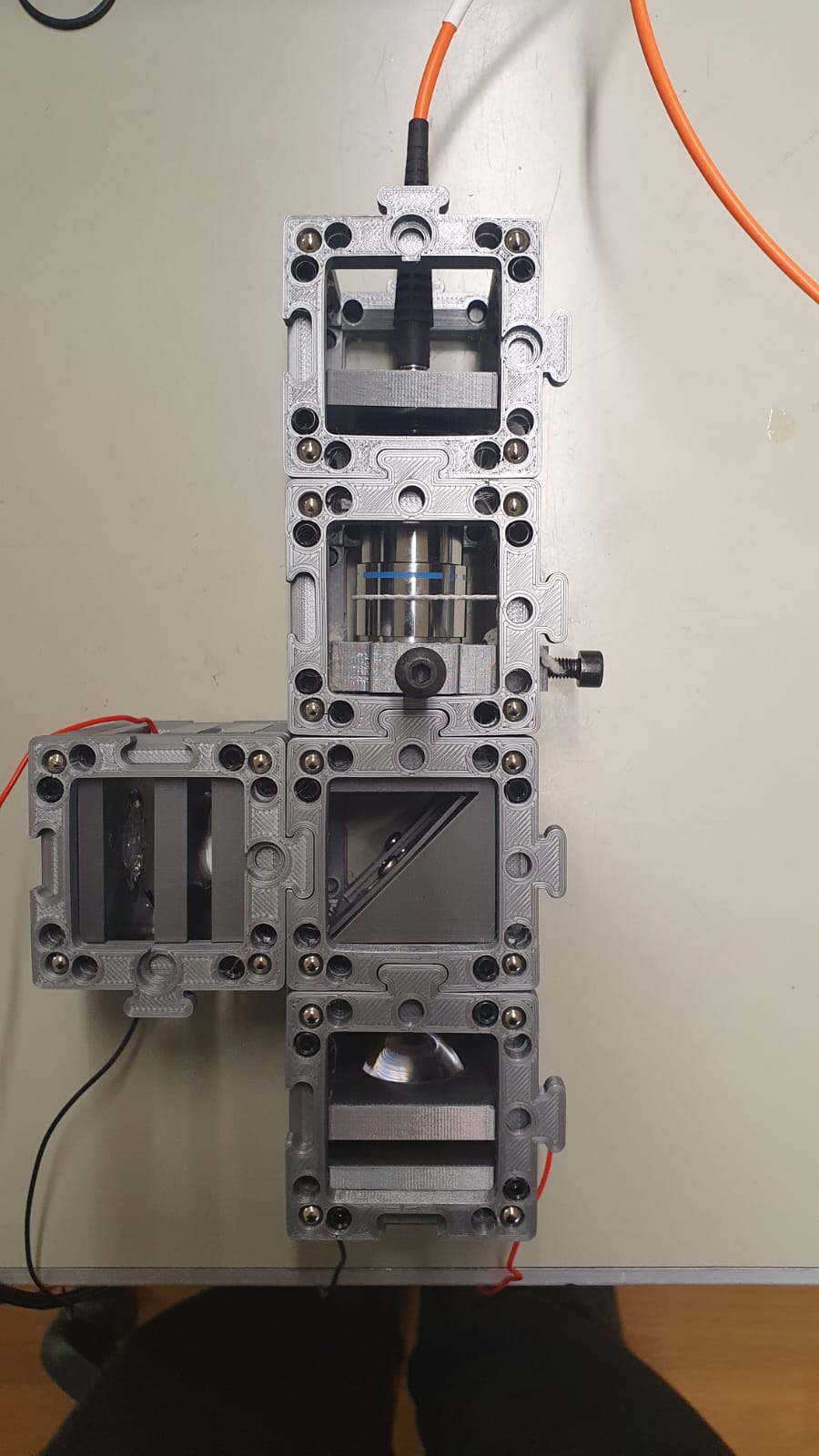
The 2nd part of the microscope should look like that :
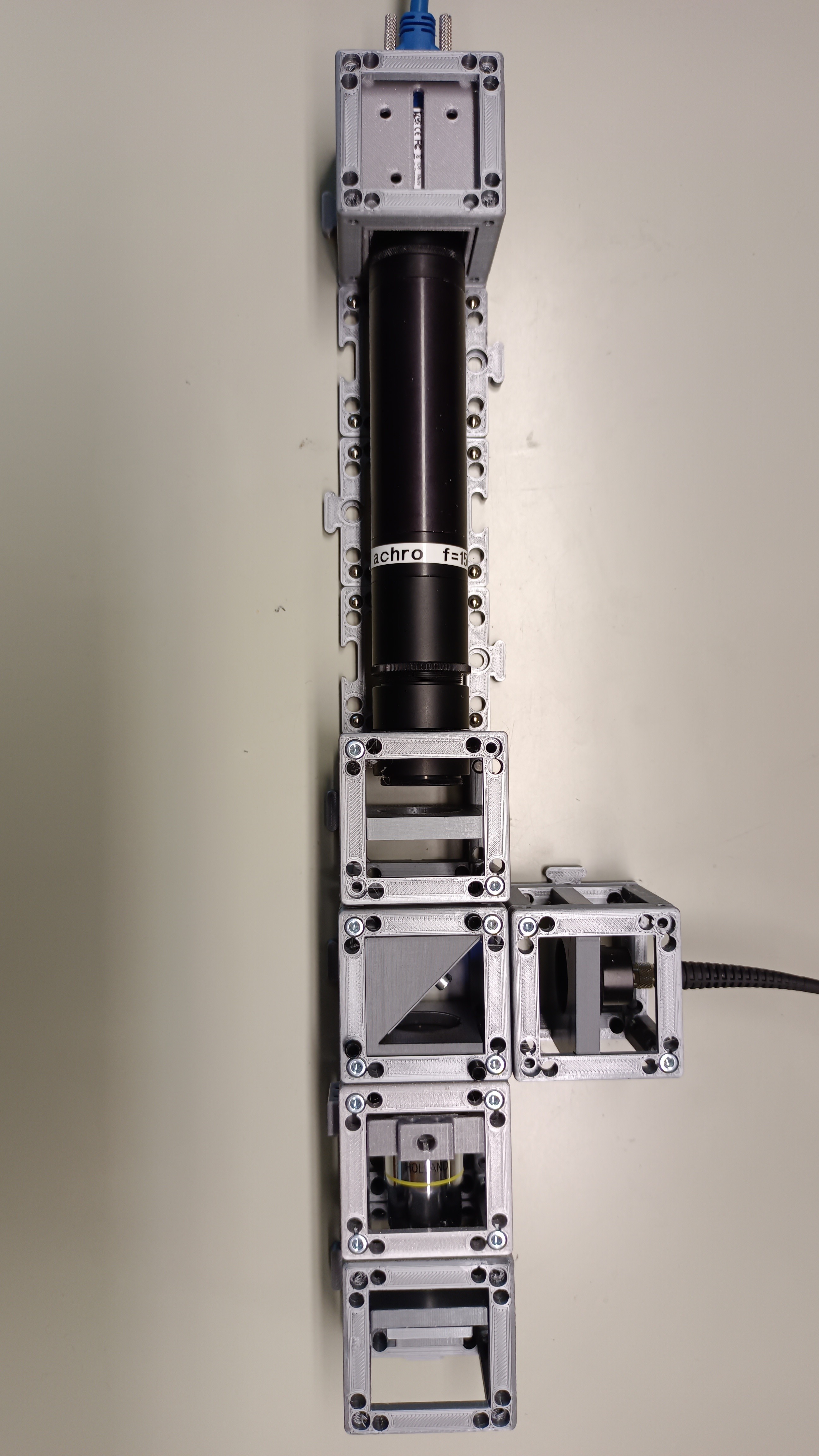
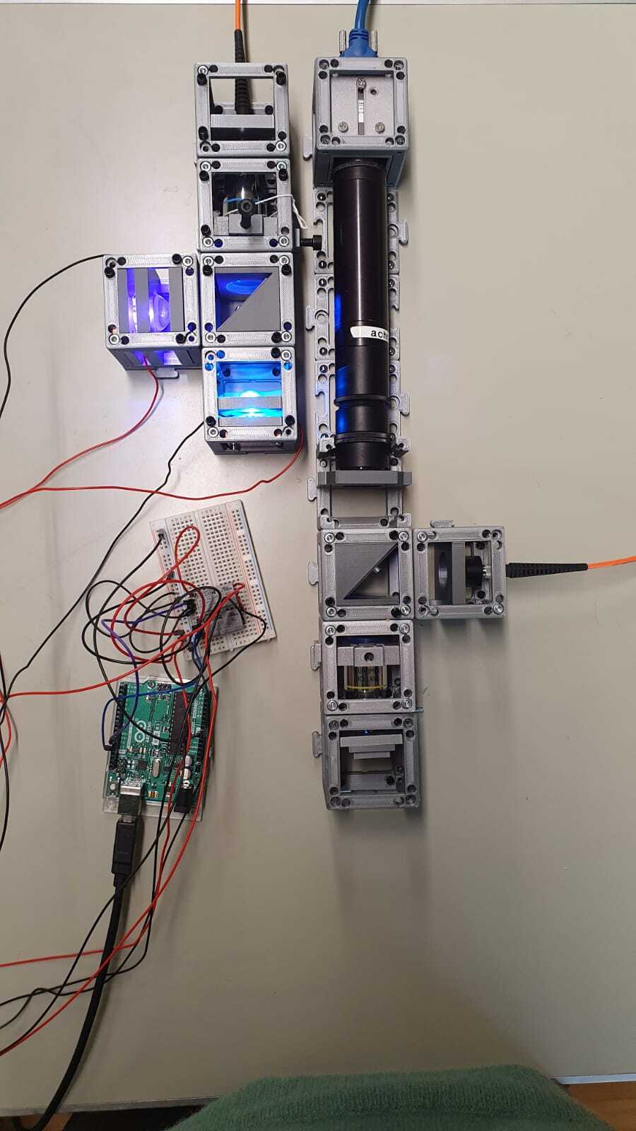
The final result should be looking like this :
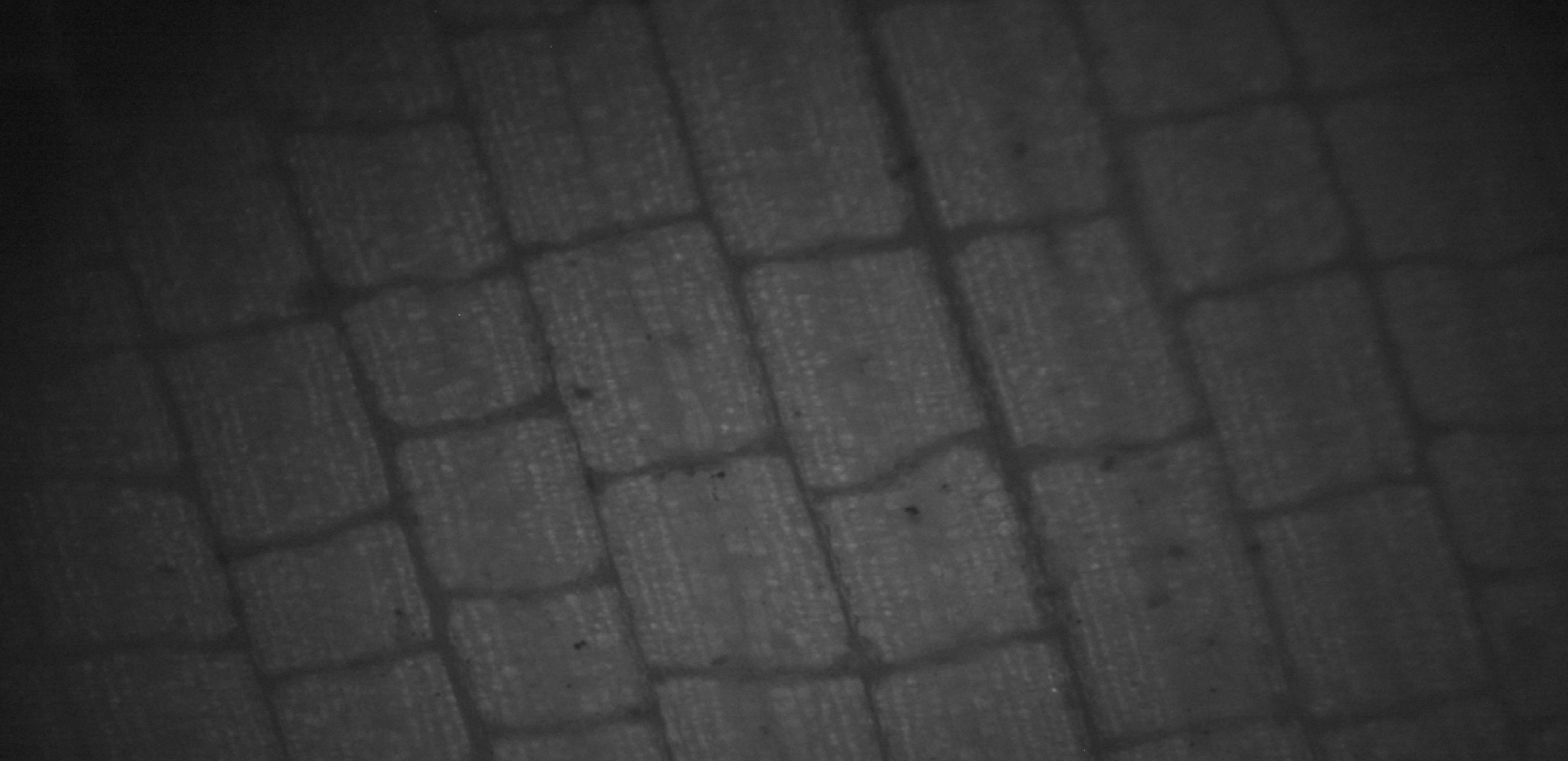
With this microscope, with managed to observe some samples using the software provided by the camera manufacturer :
You can follow the instructions in this repository to control the camera using Python.
Example of use
For an example of project using this hardware you can refer to this page